Scanning Available Networks with MKR GSM 1400
Learn how to scan nearby GSM networks in your area, and print them out in the Serial Monitor.
Introduction
In this tutorial, we will perform a scan of available GSM networks in the area. The networks available will then be printed in the Serial Monitor along with the signal strength.
Note: This tutorial was created in Sweden, and as a result, the available networks are only Swedish network operators. The results will vary depending on what location we are in.
Goals
The goals of this project are:
- Scan nearby GSM networks
- Print detected networks in the Serial Monitor.
Hardware & Software Needed
- Arduino IDE (online or offline).
- MKRGSM library installed.
- Arduino MKR GSM 1400.
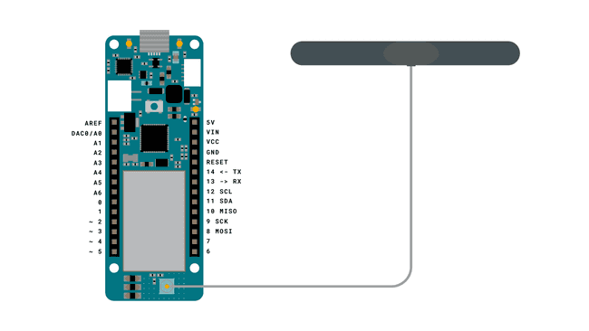
- Antenna.
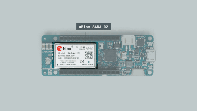
The uBlox SARA-02 Module
As every other MKR family board, the MKR GSM 1400 board has a specific module for connectivity. It is called uBlox SARA-02, and is designed to communicate over the GSM network. The High Speed Packet (HSPA) data rates can reach downlink speeds of 7.2 Mbit/s and 5.76 Mbit/s for uplink.

It is also designed to operate in temperature conditions between -40 °C to +85 °C, making it quite the durable component. It is also low on power consumption, making it ideal to use with batteries in different weather conditions!
The module also provides an interface for SIM cards, and supports both 1.8V and 3V SIM cards, which can be automatically detected.
You can find out much more information about this component in the uBlox SARA-02 datasheet.
Circuit

Programming the Board
We will now get to the programming part of this tutorial.
1. First, let's make sure we have the drivers installed. If we are using the Web Editor, we do not need to install anything. If we are using an offline editor, we need to install it manually. This can be done by navigating to Tools > Board > Board Manager.... Here we need to look for the Arduino SAMD boards (32-bits Arm® Cortex- M0+) and install it.
2. Now, we need to install the libraries needed. If we are using the Web Editor, there is no need to install anything. If we are using an offline editor, simply go to Tools > Manage libraries.., and search for MKRGSM and install it.
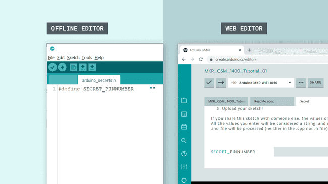
3. After the library is installed, we can now navigate to File > Examples > MKRGSM > Tools > GsmScanNetworks. This will open a new sketch window (or direct you to the sketch if you are using the Web Editor). There will also be a separate tab called
arduino_secrets.h
Note: A standard pre-paid SIM card typically have 0000 or 1234 as a pin code. This varies from operator to operator,and it is important to find out this before uploading the code. Otherwise, too many unsuccessful attempts may block the SIM card.
4. We can now take a look at some of the core functions of this sketch:
- base class for all GSM functions.GSM gsmAccess
- base class relating to scanning of available networks.GSMScanner scannerNetworks
- base class for calls that have specific diagnostic functionality with the modem.GSMModem modemTest
- connects to the GSM network with the pin number as a parameter, e.g. 0123.gsmAccess.begin(pin)
- retrieves the International Mobile Equipment Identity (IMEI) from the modem.getIMEI()
5. We can now upload the sketch to the board. The code is also available in the snippet below:
1#include <MKRGSM.h>2
3#include "arduino_secrets.h" 4// Please enter your sensitive data in the Secret tab or arduino_secrets.h5// PIN Number6const char PINNUMBER[] = SECRET_PINNUMBER;7
8// initialize the library instance9GSM gsmAccess; // include a 'true' parameter to enable debugging10GSMScanner scannerNetworks;11GSMModem modemTest;12
13// Save data variables14String IMEI = "";15
16// serial monitor result messages17String errortext = "ERROR";18
19void setup() {20 // initialize serial communications and wait for port to open:21 Serial.begin(9600);22 while (!Serial) {23 ; // wait for serial port to connect. Needed for Leonardo only24 }25
26 Serial.println("GSM networks scanner");27 scannerNetworks.begin();28
29 // connection state30 bool connected = false;31
32 // Start GSM shield33 // If your SIM has PIN, pass it as a parameter of begin() in quotes34 while (!connected) {35 if (gsmAccess.begin(PINNUMBER) == GSM_READY) {36 connected = true;37 } else {38 Serial.println("Not connected");39 delay(1000);40 }41 }42
43 // get modem parameters44 // IMEI, modem unique identifier45 Serial.print("Modem IMEI: ");46 IMEI = modemTest.getIMEI();47 IMEI.replace("\n", "");48 if (IMEI != NULL) {49 Serial.println(IMEI);50 }51}52
53void loop() {54 // scan for existing networks, displays a list of networks55 Serial.println("Scanning available networks. May take some seconds.");56 Serial.println(scannerNetworks.readNetworks());57
58 // currently connected carrier59 Serial.print("Current carrier: ");60 Serial.println(scannerNetworks.getCurrentCarrier());61
62 // returns strength and ber63 // signal strength in 0-31 scale. 31 means power > 51dBm64 // BER is the Bit Error Rate. 0-7 scale. 99=not detectable65 Serial.print("Signal Strength: ");66 Serial.print(scannerNetworks.getSignalStrength());67 Serial.println(" [0-31]");68
69}Testing It Out
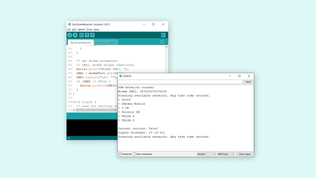
Once we have uploaded the code to the board, we can proceed by opening the Serial Monitor. This will initialize the program, and a scanning of the network will shortly begin.
If the board fails to connect to the GSM network, it will print
"Not connected"If it succeeds, it will start listing the available networks in your area.

Troubleshoot
If the code is not working, there are some common issues we can troubleshoot:
- We have not installed the MKRGSM library.
- We have entered the wrong pin number.
- We are out of coverage (no signal).
- SIM card may not be activated.
Conclusion
In this tutorial, we took a brief look at the uBlox SARA-02 module that provides the GSM connectivity to the MKR GSM 1400 board. We then configured the sketch (entered the pin number for our SIM card), and performed a scan of available networks. The list of available networks were then printed in the Serial Monitor.
This is a very basic tutorial for testing the connectivity of the MKR GSM 1400 board, and there's much much more we can do. Feel free to explore the MKRGSM library further, and try out some of the many cool functions in this library.
Suggest changes
The content on docs.arduino.cc is facilitated through a public GitHub repository. If you see anything wrong, you can edit this page here.
License
The Arduino documentation is licensed under the Creative Commons Attribution-Share Alike 4.0 license.