Cellular Connectivity with the Max Carrier & Pro 4G Module
Learn how to implement cellular connectivity using the mPCIe interface on the Portenta Max Carrier with the Arduino Pro 4G Module.
Overview
This tutorial will guide you about the Mini PCI Express (Mini PCIe) interface of the Portenta Max Carrier. We will explore the onboard Mini PCIe slot and show you how to set up and configure this interface using the Portenta X8, ensuring you can fully leverage the capabilities of your device.
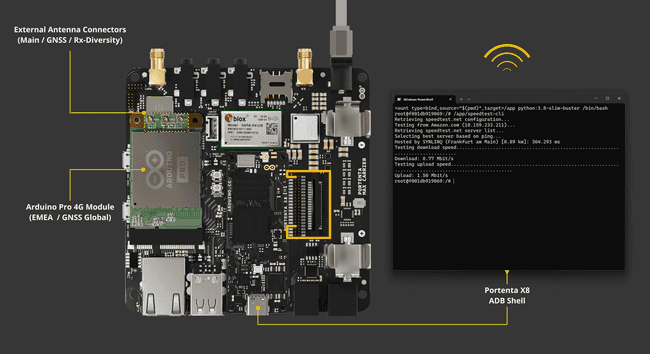
The hands-on part of this tutorial will walk you through performing a speed test with the Arduino Pro 4G Module, a Cat.4 modem mini PCIe card compatible with the Portenta Max Carrier. This test aims to provide valuable insights into the functionality and efficiency of the Portenta Max Carrier and the Pro 4G Module while demonstrating its combination's practical application and network performance potential.
Goals
- Learn about the onboard Mini PCI Express interface on the Portenta Max Carrier.
- Learn to set up and configure the Mini PCIe interface on the Portenta Max Carrier using the Portenta X8.
- Implement a speed test using a Pro 4G Module, the Portenta Max Carrier, and the Portenta X8.
Hardware and Software Requirements
Hardware Requirements
- Portenta Max Carrier (x1)
- Portenta X8 (x1)
- Pro 4G Module (GNSS Module Global / EMEA) (x1)
- Compatible antennas like the Arduino Pro 4G Module Antennas Kit (x1)
The following accessories are needed:
- USB-C® cable (USB-A to USB-C®) (x1)
- Wi-Fi® Access Point or Ethernet with Internet access (x1)
- External antenna: Main antenna, GNSS antenna, and Rx-Diversity antenna
- Power cables: Wires with a cross-sectional area ranging from 0.82 mm² to 1.3 mm², corresponding to AWG sizes 18 to 16
Software Requirements
To get your Portenta X8 ready for use with the Portenta Max Carrier, ensure it runs the most recent version of Linux. The steps to check and update your device are in this section of Portenta X8's user manual.
Your Portenta X8 should be on Linux image version 746 or newer to ensure everything works smoothly. To update your board to the latest image, use the Portenta X8 Out-of-the-box method or manually flash it, downloading the most recent version from this link.
Setting Up the Hardware Power Distribution
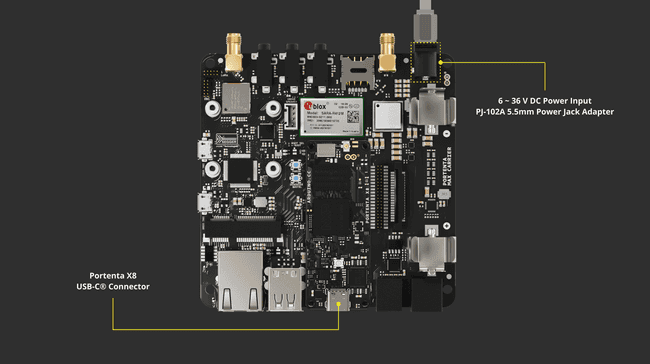
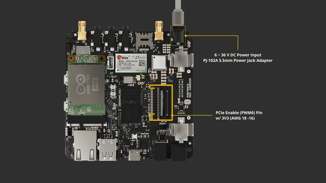
For this tutorial, you will need to connect an external 6.0 to 36.0 V power supply to the Portenta Max Carrier's Power Jack. This ensures the carrier, the Portenta X8, and any PCIe modules connected are sufficiently powered.
To ensure the power demands are met, especially for the PMIC modules' external power, we recommend using cables that conform to the appropriate electrical standards, such as the ASTM B 258 standard and can carry currents up to 2.0 A. Cables with a cross-sectional area ranging from 0.82 mm² to 1.3 mm², corresponding to AWG 18-16, should be adequate to manage 2.0 A of current.
It is advised to use a 6.0 - 36.0 V external power source when using modules like the Arduino Pro 4G Module (EMEA / GNSS Global) or other mPCIe modules, to ensure a stable power supply for both the Portenta X8 and the carrier during prolonged usage.
The following image provides the position of the Power Jack on the Portenta Max Carrier:
Mini PCI Express
Mini PCIe, short for Mini Peripheral Component Interconnect Express, is a smaller version of the PCIe interface mainly used in laptops and small devices to add features such as Wi-Fi®, Bluetooth®, and cellular connectivity.
These cards are significantly smaller than standard PCIe cards, typically measuring around 30 mm x 50.95 mm, and are designed to fit into the limited spaces of compact systems. They connect to a motherboard via a dedicated Mini PCIe slot, supporting PCIe and USB 2.0 interfaces. They are available in full-size and half-size variants.
Mini PCIe & Portenta Max Carrier
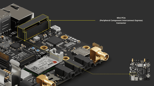
The Portenta Max Carrier features a mini PCI Express card slot designed for use with female connectors. This slot is positioned at a right angle, and the board comes equipped with two detachable supports to ease the addition of external modules. The Max Carrier is also compatible with two sizes of Mini PCIe cards. Pins 8, 10, 12, and 14 are specifically set aside for use with SIM cards.
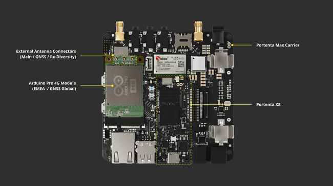
In its portfolio, Arduino has two mini PCIe modules compatible with Portenta Max Carrier, the Arduino Pro 4G Module, a Cat.4 modem mini PCIe card available in two variants: EMEA and GNSS Global.
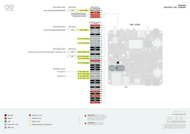
The onboard Mini PCIe slot of the Portenta Max Carrier has the following pin layout characteristics:
| Pin Number | Silkscreen Pin | Power Net | Portenta Standard Pin | High-Density Pin | Pin Detail |
|---|---|---|---|---|---|
| 2 | N/A | +3V3 PCIE (Out) | From PCIE dedicated high current 3V3 power supply | ||
| 4 | N/A | Ground | GND | J1-22, J1-31, J1-42, J1-47, J1-54, J2-24, J2-33, J2-44, J2-57, J2-70 | |
| 7 | N/A | PWM_9 | J2-68 | PCIE_CLKREQ | |
| 8 | N/A | UIM_PWR | |||
| 9 | N/A | Ground | GND | J1-22, J1-31, J1-42, J1-47, J1-54 J2-24, J2-33, J2-44, J2-57, J2-70 | |
| 10 | N/A | UIM_DATA | |||
| 11 | N/A | PCIE_CK_N | J2-19 | ||
| 12 | N/A | UIM_CLK | |||
| 13 | N/A | PCIE_CK_P | J2-17 | ||
| 14 | N/A | UIM_RST | |||
| 15 | N/A | Ground | GND | J1-22, J1-31, J1-42, J1-47, J1-54, J2-24, J2-33, J2-44, J2-57, J2-70 | |
| 18 | N/A | Ground | GND | J1-22, J1-31, J1-42, J1-47, J1-54, J2-24, J2-33, J2-44, J2-57, J2-70 | |
| 20 | N/A | ANALOG_A1 | J2-75 | W_DISABLE | |
| 21 | N/A | Ground | GND | J1-22, J1-31, J1-42, J1-47, J1-54, J2-24, J2-33, J2-44, J2-57, J2-70 | |
| 22 | N/A | PCIE_RST | J2-21 | ||
| 23 | N/A | PCIE_RX_N | J2-15 | ||
| 24 | N/A | +3V3 PCIE (Out) | From PCIE dedicated high current 3V3 power supply | ||
| 25 | N/A | PCIE_RX_P | J2-13 | ||
| 26 | N/A | Ground | GND | J1-22, J1-31, J1-42, J1-47, J1-54, J2-24, J2-33, J2-44, J2-57, J2-70 | |
| 27 | N/A | Ground | GND | J1-22, J1-31, J1-42, J1-47, J1-54, J2-24, J2-33, J2-44, J2-57, J2-70 | |
| 29 | N/A | Ground | GND | J1-22, J1-31, J1-42, J1-47, J1-54, J2-24, J2-33, J2-44, J2-57, J2-70 | |
| 31 | N/A | PCIE_TX_N | J2-11 | ||
| 33 | N/A | PCIE_TX_P | J2-9 | ||
| 34 | N/A | Ground | GND | J1-22, J1-31, J1-42, J1-47, J1-54, J2-24, J2-33, J2-44, J2-57, J2-70 | |
| 35 | N/A | Ground | GND | J1-22, J1-31, J1-42, J1-47, J1-54, J2-24, J2-33, J2-44, J2-57, J2-70 | |
| 36 | N/A | USB_D_N | USB3_N (USB HUB) | ||
| 37 | N/A | Ground | GND | J1-22, J1-31, J1-42, J1-47, J1-54, J2-24, J2-33, J2-44, J2-57, J2-70 | |
| 38 | N/A | USB_D_P | J1-26 | USB3_P (USB HUB) | |
| 39 | N/A | +3V3 PCIE (Out) | From PCIE dedicated high current 3V3 power supply | ||
| 40 | N/A | Ground | GND | J1-22, J1-31, J1-42, J1-47, J1-54, J2-24, J2-33, J2-44, J2-57, J2-70 | |
| 41 | N/A | +3V3 PCIE (Out) | From PCIE dedicated high current 3V3 power supply | ||
| 43 | N/A | Ground | GND | J1-22, J1-31, J1-42, J1-47, J1-54, J2-24, J2-33, J2-44, J2-57, J2-70 | |
| 50 | N/A | Ground | GND | J1-22, J1-31, J1-42, J1-47, J1-54, J2-24, J2-33, J2-44, J2-57, J2-70 | |
| 52 | N/A | +3V3 PCIE (Out) | From PCIE dedicated high current 3V3 power supply |
The full pinout document of the Portenta Max Carrier can also provide a graphical representation of the mini PCIe interface pinout layout. The following image represents the dedicated page from the complete pinout documentation:
Mini PCIe Interface Setup
To address the power demands and ensure reliable connections, using jumper cables that comply with appropriate electrical standards, such as ASTM B 258 standard, and can support up to 2A of current is advisable. Jumper cables with a cross-sectional area ranging from 0.82 mm² to 1.3 mm², roughly equivalent to AWG 18-16, should be sufficient for 2.0 A of current.
Such a precaution is key to preventing wire overheating and guaranteeing stable power supply to Mini PCIe-compatible devices, like Cat.4 modems. An essential setup for activating the mini PCIe interface with the Portenta Max Carrier involves the following:
- Powering the PCIE ENABLE (PWM6) pin with 3.3 V
- Correctly installing a mini PCIe module, such as a Pro 4G GNSS Module Global or a Pro 4G EMEA Module
The PCIE ENABLE (PWM6) is the 33rd pin of the High-Density Connector (HDC) Stacker Connector (J5).
Using an external power source of 6.0 to 36.0 V is important when working with an Arduino Pro 4G Module (EMEA / GNSS Global) or any other mPCIe modules because of their high power consumption. This ensures a continuous and stable power feed to the Portenta X8, the carrier, and the involved mPCIe module, especially during extended use.
Pro 4G Module - Cat.4 Modem
The Cat.4 modem, compatible with mPCIe interfaces, leverages LTE (Long Term Evolution) standards to provide high-speed data transmission across various electronic devices.
These modems offer substantial data speeds, reaching up to 150 Mbps for downloads and 50 Mbps for uploads, making them ideal for a range of IoT and Industrial activities like remote monitoring, Smart Cities and buildings, smart farming and much more.
Designed with the mPCIe form factor, Cat.4 modems fit snugly in compact electronics such as laptops, tablets, and IoT devices with 4G connectivity. They also support older 3G and 2G networks, ensuring wide network coverage.
The Portenta Max Carrier uses this modem through its built-in mini PCIe interface. The Arduino Pro 4G Module is a key feature in this configuration.
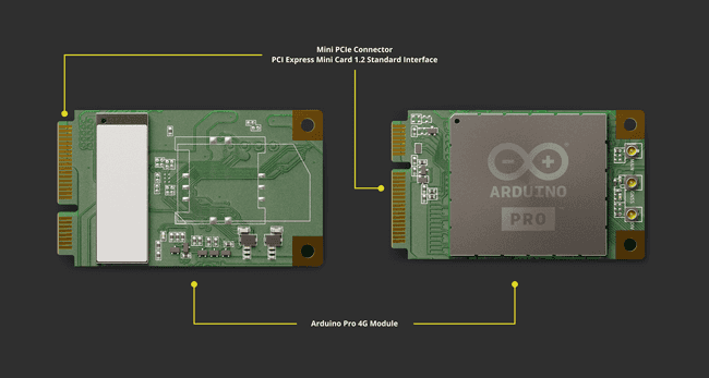
This module has two versions: EMEA and Global (including the US). It can be used with various Portenta boards to help develop expansive smart city/building projects and to support remote maintenance and fleet management.
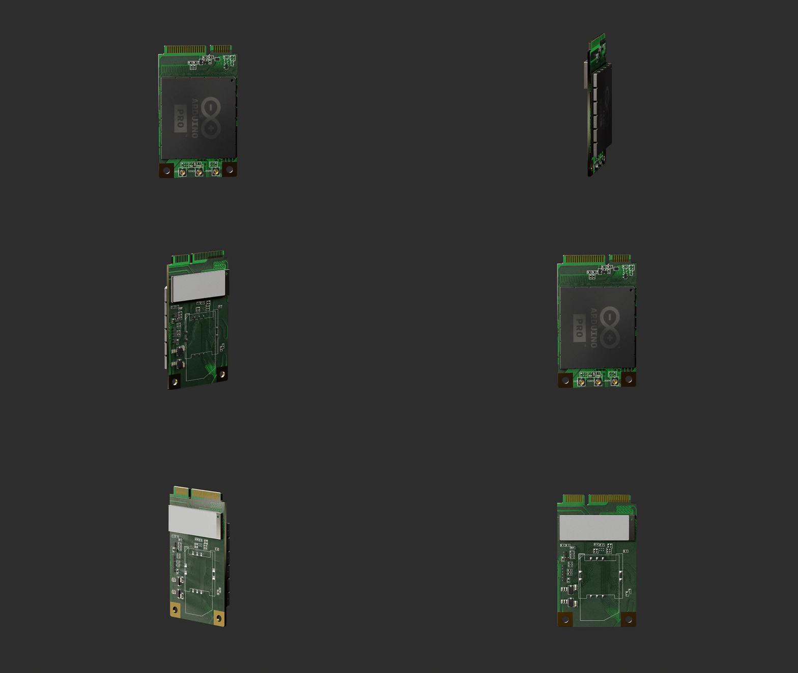
Make sure to attach external antennas to the Pro 4G Module to work correctly with wireless signals. There are three external antenna connectors: a main antenna connector, an Rx-diversity antenna connector, and a GNSS antenna connector. The impedance of the antenna connectors are 50 Ω.
Complete Hardware Setup
The image below illustrates the expected setup, showcasing the integration of the Portenta X8 and Pro 4G Module with the Portenta Max Carrier.
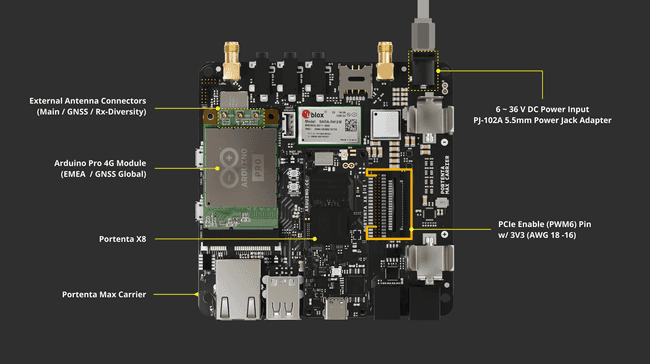
Please ensure the mini PCIe power configuration is set as outlined in the Mini PCIe Power Distribution section. The Portenta X8 requires the PCIE ENABLE (PWM6) pin to be connected to a VCC (3V3) pin.
Please use a 6.0 - 36.0 V external power source when using an Arduino Pro 4G Module (EMEA / GNSS Global) or any other mPCIe modules due to their high power consumption. This is important for maintaining a stable power supply to the Portenta X8, the carrier, and the involved mPCIe module, particularly for extended periods of use.
Instructions
Accessing the Mini PCIe Interface
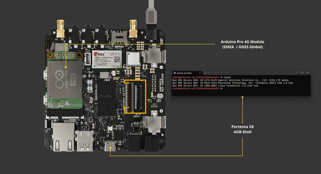
You can check if the mini PCIe module is properly installed and detected by the Portenta X8 by using the Portenta Max Carrier USB's functionality. Since the mini PCIe lanes on the Portenta Max Carrier include USB lines, and the Pro 4G Module functions as a USB device, it is possible to use them to verify a correct setup.
To ensure the Pro 4G Module is powered up and recognized by the Portenta X8 along with the Portenta Max Carrier, use the following command:
1lsusbThis command lists the USB devices recognized by the Portenta X8. If the Pro 4G Module is correctly detected, you will see results similar to the ones shown in the following image.
Setting Up Via Out-Of-The-Box Experience
Setting up the modem is easy with the Out-Of-The-Box process on the Portenta X8 paired with the Portenta Max Carrier.
If you are new to the Out-Of-The-Box experience of the Portenta X8, we recommend reviewing the Out-Of-The-Box Experience section of the Portenta X8 User Manual for a better understanding before you continue.
Proceed to the Out-Of-The-Box dashboard on the Portenta X8.
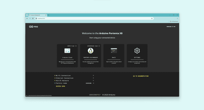
In this dashboard, you will find the Settings option. Please click on this option to proceed to the next step.
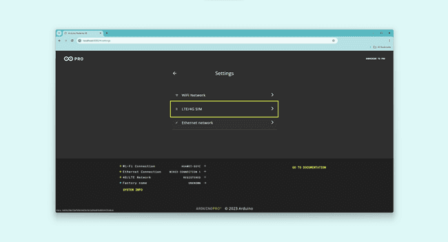
In the Settings, choose the LTE/4G Sim option to start configuring the modem.
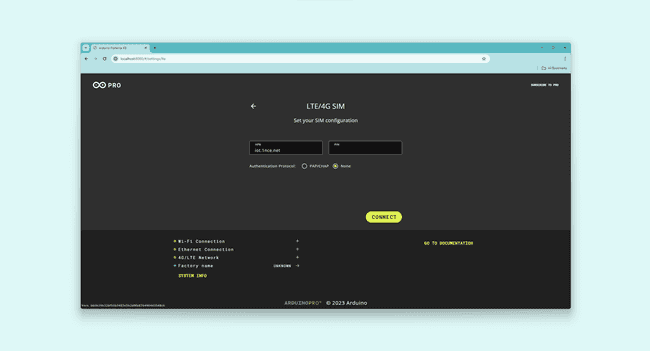
For the LTE/4G Sim settings, you will need to provide:
- APN
- PIN (if available)
You will also need to choose an Authentication Protocol, either:
- PAP/CHAP
- NONE
PAP (Password Authentication Protocol) sends passwords as clear text, suitable for low-security or legacy environments. At the same time, CHAP (Challenge-Handshake Authentication Protocol) offers enhanced security through a three-step verification process and encrypted passwords, providing better protection than PAP.
Enter these details based on your SIM card's requirements. Once done, the 4G/LTE Network connection status will be displayed at the bottom left of the Out-Of-The-Box dashboard.
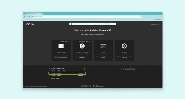
A brief notification will confirm the successful network connection by the Portenta X8 if a network is available. You can view more details about the connection by selecting SYSTEM INFO.
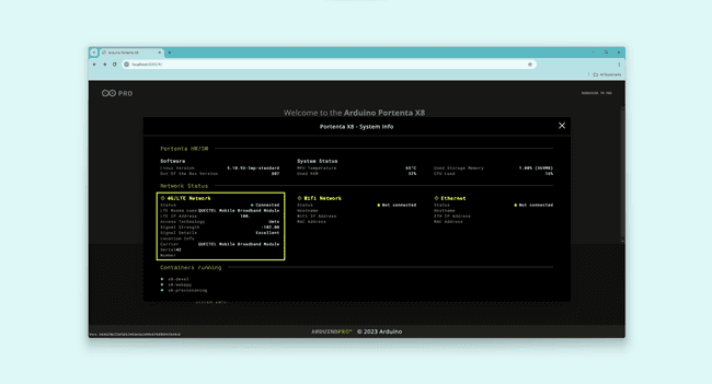
You have successfully connected the Portenta X8 to a 4G/LTE network via the Portenta Max Carrier and the Pro 4G Module.
Setting Up Using Linux Environment
The Pro 4G Module can be managed via ADB shell on the Portenta X8's Linux environment. A series of commands is used to apply the necessary overlays for the Portenta X8 and the Portenta Max Carrier.
To check the existing device tree overlay configurations, which play a key role in managing hardware features and customizing the system, you can use this command:
1fw_printenv overlaysThis command uses the
fw_printenvThis might involve enabling extra peripherals, setting up pin configurations, or turning on specific hardware functionalities, thus offering a versatile means for customizing hardware settings. Among the overlays that should be visible is:
1ov_carrier_max_pcie_miniIf it is not present, the following steps will help you set the needed overlays to use the mini PCIe interface on the Portenta Max Carrier. There are two ways to set up the overlay configuration for the mPCIe interface:
- Via tenta-config based on the
frameworktenta - Via ADB shell
Overlay Configuration Via Tenta-Config
You can apply the necessary overlays to activate mini PCIe on the Portenta Max Carrier with the Portenta X8 by using the tenta-config process.
Start by accessing the docker container named x8-devel with this command:
1docker exec -it x8-devel shThis command uses docker exec to start a new shell session inside the active x8-devel container. The
-itFind the tenta_runner Python® script with the help of this command:
1find / -name *.pyThis command begins at the root directory and recursively searches for files with a
.pyOnce you have found tenta_runner.py, move to its directory with this command:
1cd /root/examples/tenta-configRun the tenta_runner.py script using the following command:
1python tenta_runner.pyThe script will activate a user interface within the
tenta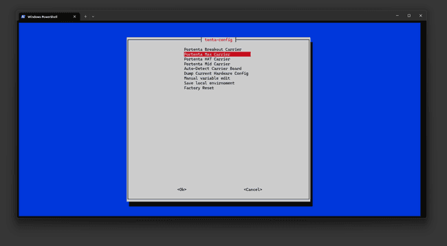
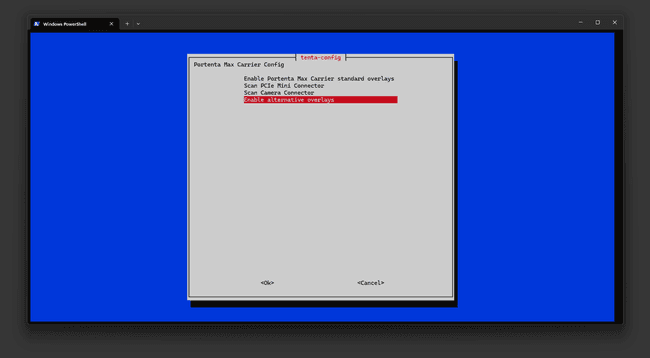
It will then show a list of available options that can be executed within the Portenta Max Carrier platform. Here, the Enable alternative overlays option will be selected.
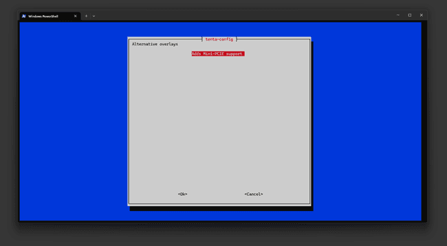
It will open a new window displaying the Adds Mini-PCIE support option. Please select the Adds Mini-PCIE support option.
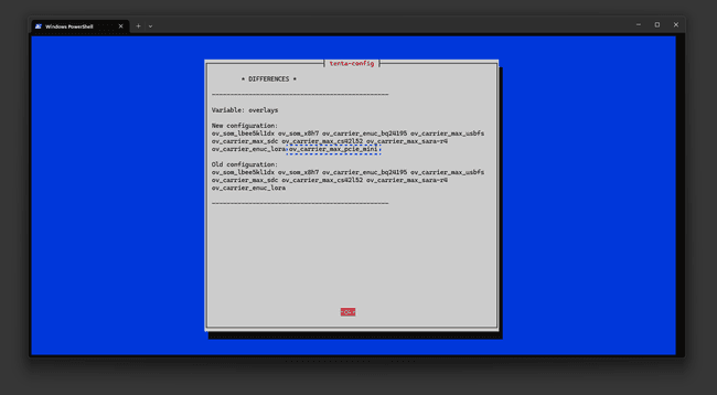
It will prompt a message showing a new set of overlays that will be applied once modified.
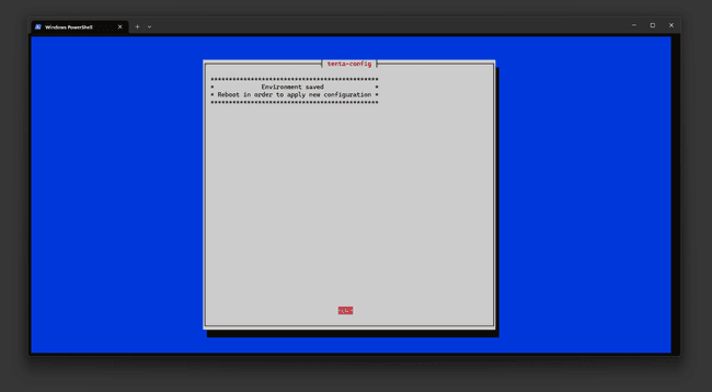
Select Ok to confirm, and the device will be configured with the overlays for mini PCIe support.
Overlay Configuration Via ADB Shell
The following commands are used to set the required overlays to add mini PCIe support on the Portenta X8 and the Portenta Max Carrier.
1fw_setenv carrier_custom 11fw_setenv is_on_carrier yes1fw_setenv carrier_name maxThe previous commands are used to set environment variables, which we will use to set and use the needed overlays to link the mini PCIe interface under its profile. The overlays are as follows and set using the following command:
1fw_setenv overlays 'ov_som_lbee5kl1dx ov_som_x8h7 ov_carrier_enuc_bq24195 ov_carrier_max_usbfs ov_carrier_max_sdc ov_carrier_max_cs42l52 ov_carrier_max_pcie_mini'Once the overlays are set, please reboot the Portenta X8 to ensure the configuration has been applied correctly.
Connecting & Testing Network Connectivity
With the overlays configured, the setup process involves bringing down the
wwan01ip link set dev wwan0 down1echo Y > /sys/class/net/wwan0/qmi/raw_ip1ip link set dev wwan0 upFollowing that, use
qmicli1qmicli --device=/dev/cdc-wdm0 --device-open-proxy --uim-get-card-status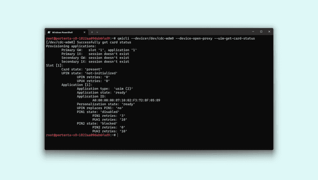
1qmicli --device=/dev/cdc-wdm0 --device-open-proxy --wds-start-network="ip-type=4,apn=iot.1nce.net" --client-no-release-cid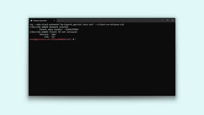
After establishing the network connection, the
udhcpc1udhcpc -q -f -n -i wwan0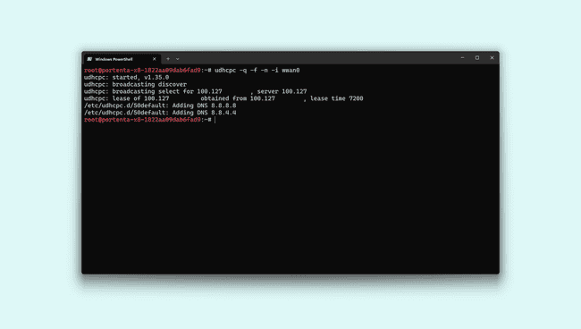
We now have the Pro 4G Module with the Portenta X8 on the Porteta Max Carrier ready for use. To test the connection speed, perform a speed test by downloading the
speedtest-cli1wget -O speedtest-cli https://raw.githubusercontent.com/sivel/speedtest-cli/master/speedtest.py1chmod +x speedtest-cli1docker run python:3.8-slim-buster1docker run -it --mount type=bind,source="$(pwd)",target=/app python:3.8-slim-buster /bin/bash1/app/speedtest-cliAfter the speed test, you might observe results similar to the following image.

The download and upload speed may vary depending on the region.
For a more streamlined approach, you can use the following single-line command:
1nmcli c add type gsm ifname cdc-wdm0 con-name wwan0 apn hologram connection.autoconnect yesIf your SIM card requires a PIN, adjust the command as follows:
1nmcli c add type gsm ifname cdc-wdm0 con-name wwan0 apn mobile.vodafone.it gsm.pin <PIN>Conclusion
In this tutorial, you have learned the key steps to use and configure the mini PCI Express interface on the Portenta Max Carrier with the Portenta X8. You will be able to manage the mini PCIe interface and use the Pro 4G Module via the Out-Of-The-Box experience method,
tentaSupport
If you encounter any issues or have questions while working with the Portenta Max Carrier, we provide various support resources to help you find answers and solutions.
Help Center
Explore our Help Center, which offers a comprehensive collection of articles and guides for the Portenta Max Carrier. The Arduino Help Center is designed to provide in-depth technical assistance and help you make the most of your device.
Forum
Join our community forum to connect with other Portenta Max Carrier users, share your experiences, and ask questions. The forum is an excellent place to learn from others, discuss issues, and discover new ideas and projects related to the Portenta Max Carrier.
Contact Us
Please get in touch with our support team if you need personalized assistance or have questions not covered by the help and support resources described before. We're happy to help you with any issues or inquiries about the Portenta Max Carrier.
Suggest changes
The content on docs.arduino.cc is facilitated through a public GitHub repository. If you see anything wrong, you can edit this page here.
License
The Arduino documentation is licensed under the Creative Commons Attribution-Share Alike 4.0 license.