MicroPython and the IMU Machine Learning Core Features
Learn how to use the Machine Learning Core (MLC) feature of the inertial module of the Nano RP2040 Connect.
Introduction
In this tutorial, you will learn how to access the Machine Learning Core feature provided by the LSM6DSOX, the onboard Inertial Measurement Unit of the Arduino® Nano RP2040 Connect using MicroPython and the OpenMV IDE. The STMicroelectronics® Machine Learning Core combines several hardware and software tools that help designers implement gesture and activity recognition with Artificial Intelligence at the Edge in sensors through machine learning algorithms based on decision tree classifiers.
Note: Please refer to this installation guide if you need help setting up your environment to use your Nano RP2040 Connect board with MicroPython and the OpenMV IDE.
Goals
The goals of this tutorial are:
- Detect motion activity such as vibration and head gestures using the Machine Learning Core feature of the Nano RP2040 Connect onboard inertial measurement unit.
- Print motion activity in the Serial Terminal of the OpenMV IDE.
Hardware and Software Needed
- Arduino Nano RP2040 Connect board.
- OpenMV IDE.
- Micro-USB cable (x1).
Inertial Measurement Unit
An Inertial Measurement Unit (IMU) is a device that can measure an object's specific gravity and angular rate. Typically, an IMU consists of three devices:
- Gyroscope: a device that measures the system's angular rate.
- Accelerometer: a device that measures the system's specific force/acceleration.
- Magnetometer: an optional device that measures the surrounding magnetic field of the system.
IMU's are typically used to capture movement data of a device or a system. The onboard IMU of the Nano RP2040 Connect, the LSM6DSOX from STMicroelectronics®, has an embedded hardware processing engine dedicated to real-time machine learning computing; this means that some machine learning algorithms were moved from the application processor to the LSM6DSOX directly. STMicroelectronics named this embedded processing engine of the LSM6DSOX Machine Learning Core (MLC).
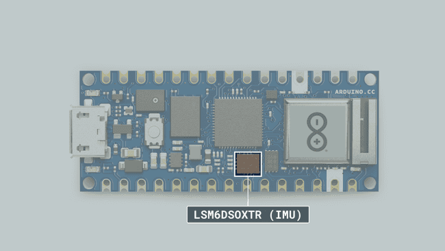
In the MLC, machine learning processing is implemented through a decision-tree logic. A decision tree is a mathematical tool composed of a series of configurable nodes; each node is characterized by an "if-then-else" condition where an input signal (represented by statistical parameters calculated from the sensor data) is evaluated against a certain threshold. The decision tree results can be read from the application processor at any time and there is also the possibility to generate an interrupt for every change in the result in the decision tree.
Using the MLC for Vibration Monitoring
We will use the LSM6DSOX accelerometer from our Nano RP2040 Connect board, its MLC, and a pre-trained model to implement a simple vibration monitoring script. With this script, and the pre-trained model, three types of vibrations can be detected:
- No vibration.
- Low vibration.
- High vibration.
Circuit
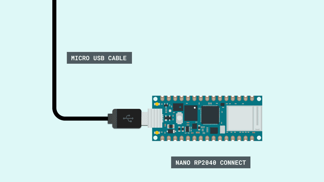
Acceleromenter Configuration
For the vibration monitoring application, the LSM6DSOX accelerometer is configured with ±4g full scale and a 26 Hz output data rate; any sensor orientation is allowed.
Machine Learning Core Configuration
For the vibration monitoring application, just one feature has been used (peak-to-peak) and applied to the accelerometer norm squared input. The MLC runs at 26 Hz, computing features on windows of 16 samples (more or less, every 0.6 seconds). One decision tree with just two nodes has been configured to detect the different classes; an interrupt (pulsed and active high) is generated every time a new vibration type is detected.
Vibration Monitoring Code
We will now get to the programming part of this tutorial.
1. Setting Up
Plug in your Nano RP2040 Connect board to your computer and open the OpenMV IDE; press the "Connect" button that is located in the lower left corner of the IDE.
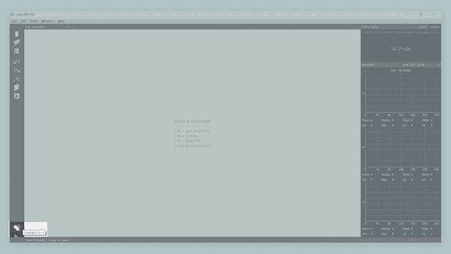
The "Connect" button should change now. When the board is connected, information about it should be displayed in the lower status bar. Make sure that the latest OpenMV firmware is uploaded to your board, you can check the latest OpenMV firmware release here.
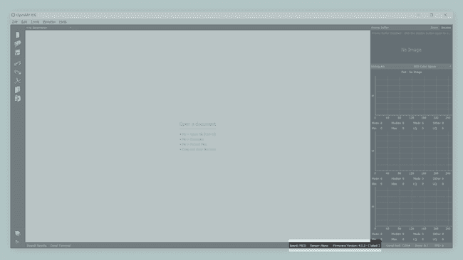
Now, download the pre-trained model for the vibration monitoring application and copy it to your Nano RP2040 Connect board storage. The pre-trained model for the vibration monitoring can be found here as well other pre-trained models for different examples and applications.
2. Creating the Script
First, let's import some modules into the script that will help you control your board:
1import time2from lsm6dsox import LSM6DSOX3from machine import Pin, I2CNow, let's enable interrupts. At start, the interrupt flag is set to
FALSE1INT_MODE = True # Enable interrupts2INT_FLAG = False # At start, no pending interruptsNow, let's define the IMU interrupt handler; the interrupt handler is a function that is going to be executed when an interrupt from the IMU is generated. This function, when executed, is going to update the value of
INT_FLAGTrue1# Interrupt handler function2def imu_int_handler(pin):3 # This function defines the IMU interrupt handler function4 global INT_FLAG5 INT_FLAG = TrueNow, let's configure the IMU interrupt in our board. For configuring the interrupt, we need to specify the interrupt pin (GPIO 24 for this example), the interrupt handler function and the type of trigger of the interrupt (rising edge, this means a change from low to high):
1# External interrupt configuration (IMU)2if (INT_MODE == True):3 int_pin = Pin(24)4 int_pin.irq(handler = imu_int_handler, trigger = Pin.IRQ_RISING)Now, let's create a I2C object, passing pins 13 and 12 for SCL and SDA:
1# I2C object initialization2i2c = I2C(0, scl=Pin(13), sda=Pin(12))Now, let's configure the pre-trained model for the vibration monitoring application. For configuring the pre-trained model in our sketch, we must define first the name of the file we copied into our Nano RP2040 Connect board storage before, the labels of the model and then initialize an IMU object with this file; notice that the selected data rate and scale matches the MLC data rate and scale described before here:
1# Pre-trained model definition and IMU object initialization2UCF_FILE = "lsm6dsox_vibration_monitoring.ucf"3UCF_LABELS = {0: "no vibration", 1: "low vibration", 2: "high vibration"}4lsm = LSM6DSOX(i2c, gyro_odr = 26, accel_odr = 26, gyro_scale = 2000, accel_scale = 4, ucf = UCF_FILE)Now that we have the IMU ready, its time to start getting interrupts from it when a certain type of vibration is recognized. For this, we are going to keep looking for the interrupt flag
INT_FLAGFALSETRUEINT_FLAGTRUE1print("\n--------------------------------")2print("- Vibration Monitoring Example -")3print("--------------------------------\n")4print("- MLC configured...\n")5
6while (True):7 if (INT_MODE):8 if (INT_FLAG):9 # Interrupt detected, read the MLC output and translate it to a human readable description10 INT_FLAG = False11 print("-", UCF_LABELS[lsm.read_mlc_output()[0]])12 else:13 buf = lsm.read_mlc_output()14 if (buf != None):15 print(UCF_LABELS[buf[0]])Complete Script
If you choose to skip the code building section, the complete script can be found below:
1# LSM6DSOX IMU MLC (Machine Learning Core) Example.2# Application: Vibration monitoring.3# Original example script by OpenMV team, modified by José Bagur.4
5import time6from lsm6dsox import LSM6DSOX7from machine import Pin, I2C8
9INT_MODE = True # Enable interrupts10INT_FLAG = False # At start, no pending interrupts11
12# Define the interrupt handler function.13def imu_int_handler(pin):14 global INT_FLAG15 INT_FLAG = True16
17# Configure the external interrupt (IMU).18if (INT_MODE == True):19 int_pin = Pin(24)20 int_pin.irq(handler = imu_int_handler, trigger = Pin.IRQ_RISING)21
22# Initialize an I2C object. 23i2c = I2C(0, scl=Pin(13), sda=Pin(12))24
25# Pre-trained model configuration26# NOTE: Selected data rate and scale must match the MLC data rate and scale configuration.27UCF_FILE = "lsm6dsox_vibration_monitoring.ucf"28UCF_LABELS = {0: "no vibration", 1: "low vibration", 2: "high vibration"}29lsm = LSM6DSOX(i2c, gyro_odr = 26, accel_odr = 26, gyro_scale = 2000, accel_scale = 4, ucf = UCF_FILE)30
31print("\n--------------------------------")32print("- Vibration Monitoring Example -")33print("--------------------------------\n")34print("- MLC configured...\n")35
36while (True):37 if (INT_MODE):38 if (INT_FLAG):39 # Interrupt detected, read the MLC output and translate it to a human readable description40 INT_FLAG = False41 print("-", UCF_LABELS[lsm.read_mlc_output()[0]])42 else:43 buf = lsm.read_mlc_output()44 if (buf != None):45 print(UCF_LABELS[buf[0]])Now you are ready to upload and run the script to your board. Press the green "Start" button that is located in the lower left corner of the IDE.
Testing Vibration Detection
After successfully uploading the code to the board, open OpenMV IDE's Serial Terminal. If the board is not moving at all, e.g. standing still at a table, the Serial Terminal will print
No vibrationLow vibrationHigh vibration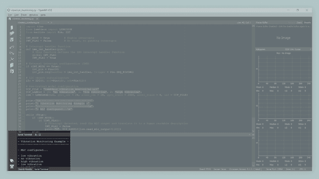
Troubleshoot
If the code is not working, there are some common issues you can troubleshoot:
- Your board doesn't have uploaded the latest release of the OpenMV firmware.
- Your board doesn't have uploaded the pre-trained model into its storage.
- An incorrect pin number was assigned to the IMU interrupt. Make sure that pin 24 is assigned to it.
- You have a faulty Micro-USB cable; try with a different cable.
Conclusion
In this tutorial, you have learned how to use the Nano RP2040 Connect IMU's MLC with a pre-trained model to detect various activity types. With these embedded machine learning capabilities, certain types of motion can be easily detected by the onboard IMU of the Nano RP2040 Connect. If you want more learn more about the MLC from STMicroelectronics, check out this repository from STMicroelectronics on GitHub that provides detailed information, examples and configurations of the MLC.
Suggest changes
The content on docs.arduino.cc is facilitated through a public GitHub repository. If you see anything wrong, you can edit this page here.
License
The Arduino documentation is licensed under the Creative Commons Attribution-Share Alike 4.0 license.